Showing posts with label Cisco. Show all posts

Sunday, January 22, 2017

The OSI Reference Model

The OSI model provides an extensive list of functions and services that can occur at each layer. It also describes the interaction of each layer with the layers directly above and below. The TCP/IP protocols discussed in this course are structured around both the OSI and TCP/IP models. Click each layer of the OSI model to view the details.

The functionality of each layer and the relationship between layers will become more evident throughout this course as the protocols are discussed in more detail.

Note: Whereas the TCP/IP model layers are referred to only by name, the seven OSI model layers are more often referred to by number rather than by name. For instance, the physical layer is referred to as Layer 1 of the OSI model.

Monday, January 16, 2017

Lab - Researching Networking Standards

In this lab, you will complete the following objectives:

  • Part 1: Research Networking Standards Organizations


  • Part 2: Reflect on Internet and Computer Networking Experience


Lab - Researching Networking Standards

Saturday, January 14, 2017

Internet Standards

Standards organizations are usually vendor-neutral, non-profit institutions established to develop and promote the concept of open standards. Various organizations have different responsibilities for promoting and creating standards for the TCP/IP protocol.

Standards organizations shown in Figure 1 include:

  • Internet Society (ISOC) – Responsible for promoting the open development and evolution of Internet use throughout the world.


  • Internet Architecture Board (IAB) - Responsible for the overall management and development of Internet standards.


  • Internet Engineering Task Force (IETF) - Develops, updates, and maintains Internet and TCP/IP technologies. This includes the process and documents for developing new protocols and updating existing protocols know as Request for Comments (RFC) documents.


  • Internet Research Task Force (IRTF) - Focused on long-term research related to Internet and TCP/IP protocols such as Anti-Spam Research Group (ASRG), Crypto Forum Research Group (CFRG), and Peer-to-Peer Research Group (P2PRG).


Standards organizations shown in Figure 2 include:

  • Internet Corporation for Assigned Names and Numbers (ICANN) - Based in the United States, coordinates IP address allocation, the management of domain names, and assignment of other information used TCP/IP protocols.


  • Internet Assigned Numbers Authority (IANA) - Responsible for overseeing and managing IP address allocation, domain name management, and protocol identifiers for ICANN.

Friday, January 13, 2017

TCP/IP Protocol Suite

Today, the TCP/IP protocol suite includes many protocols, as shown in the figure. Click each protocol to view the acronym’s translation and description. The individual protocols are organized in layers using the TCP/IP protocol model: Application, Transport, Internet, and Network Access Layers. TCP/IP protocols are specific to the Application, Transport, and Internet layers. The network access layer protocols are responsible for delivering the IP packet over the physical medium. These lower layer protocols are developed by various standards organizations.

The TCP/IP protocol suite is implemented as a TCP/IP stack on both the sending and receiving hosts to provide end-to-end delivery of applications over a network. The Ethernet protocols are used to transmit the IP packet over the physical medium used by the LAN.

Thursday, January 12, 2017

Development of TCP/IP

The first packet switching network and predecessor to today’s Internet was the Advanced Research Projects Agency Network (ARPANET), which came to life in 1969 by connecting mainframe computers at four locations. ARPANET was funded by the U.S. Department of Defense for use by universities and research laboratories.

Click through the timeline in the figure to see details about the development of other network protocols and applications.

Monday, January 9, 2017

Protocol Interaction

Communication between a web server and web client is an example of an interaction between several protocols. The protocols shown in the figure include:


  • HTTP - is an application protocol that governs the way a web server and a web client interact. HTTP defines the content and formatting of the requests and responses that are exchanged between the client and server. Both the client and the web server software implement HTTP as part of the application. HTTP relies on other protocols to govern how the messages are transported between the client and server.


  • TCP - is the transport protocol that manages the individual conversations. TCP divides the HTTP messages into smaller pieces, called segments. These segments are sent between the web server and client processes running at the destination host. TCP is also responsible for controlling the size and rate at which messages are exchanged between the server and the client.


  • IP - is responsible for taking the formatted segments from TCP, encapsulating them into packets, assigning them the appropriate addresses, and delivering them to the destination host.


  • Ethernet - is a network access protocol that describes two primary functions: communication over a data link and the physical transmission of data on the network media. Network access protocols are responsible for taking the packets from IP and formatting them to be transmitted over the media.

Sunday, January 8, 2017

Rules that Govern Communications

A group of inter-related protocols necessary to perform a communication function is called a protocol suite. Protocol suites are implemented by hosts and networking devices in software, hardware or both.

One of the best ways to visualize how the protocols within a suite interact is to view the interaction as a stack. A protocol stack shows how the individual protocols within a suite are implemented. The protocols are viewed in terms of layers, with each higher level service depending on the functionality defined by the protocols shown in the lower levels. The lower layers of the stack are concerned with moving data over the network and providing services to the upper layers, which are focused on the content of the message being sent.

As the figure shows, we can use layers to describe the activity occurring in our face-to-face communication example. At the bottom, the physical layer, we have two people, each with a voice that can say words out loud. In the middle, the rules layer, we have an agreement to speak in a common language. At the top, the content layer, there are words that are actually spoken. This is the content of the communication.

Tuesday, January 3, 2017

Message Timing

These are the rules of engagement for message timing.

Access Method

Access method determines when someone is able to send a message. If two people talk at the same time, a collision of information occurs and it is necessary for the two to back off and start again, as shown in Figure 1. Likewise, it is necessary for computers to define an access method. Hosts on a network need an access method to know when to begin sending messages and how to respond when collisions occur.

Flow Control

Timing also affects how much information can be sent and the speed that it can be delivered. If one person speaks too quickly, it is difficult for the other person to hear and understand the message, as shown in Figure 2. In network communication, source and destination hosts use flow control methods to negotiate correct timing for successful communication.

Response Timeout

If a person asks a question and does not hear a response within an acceptable amount of time, the person assumes that no answer is coming and reacts accordingly, as shown in Figure 3. The person may repeat the question, or may go on with the conversation. Hosts on the network also have rules that specify how long to wait for responses and what action to take if a response timeout occurs.

Message Size

Another rule of communication is size. When people communicate with each other, the messages that they send are usually broken into smaller parts or sentences. These sentences are limited in size to what the receiving person can process at one time, as shown in Figure 1. An individual conversation may be made up of many smaller sentences to ensure that each part of the message is received and understood. Imagine what it would be like to read this course if it all appeared as one long sentence; it would not be easy to read and comprehend.

Likewise, when a long message is sent from one host to another over a network, it is necessary to break the message into smaller pieces, as shown in Figure 2. The rules that govern the size of the pieces, or frames, communicated across the network are very strict. They can also be different, depending on the channel used. Frames that are too long or too short are not delivered.

The size restrictions of frames require the source host to break a long message into individual pieces that meet both the minimum and maximum size requirements. The long message will be sent in separate frames, with each frame containing a piece of the original message. Each frame will also have its own addressing information. At the receiving host, the individual pieces of the message are reconstructed into the original message.

Monday, January 2, 2017

Rule Establishment

Before communicating with one another, individuals must use established rules or agreements to govern the conversation. For example, consider Figure 1, protocols are necessary for effective communication. These rules, or protocols, must be followed in order for the message to be successfully delivered and understood. Protocols must account for the following requirements:

  • An identified sender and receiver


  • Common language and grammar


  • Speed and timing of delivery


  • Confirmation or acknowledgment requirements


The protocols that are used in network communications share many of these fundamental traits. In addition to identifying the source and destination, computer and network protocols define the details of how a message is transmitted across a network. Common computer protocols include the requirements shown in Figure 2. Each of these will be discussed in more detail.

Communication Fundamentals

A network can be as complex as devices connected across the Internet, or as simple as two computers directly connected to one another with a single cable, and anything in-between. Networks can vary in size, shape, and function. However, simply having a wired or wireless physical connection between end devices is not enough to enable communication. For communication to occur, devices must know “how” to communicate.

People exchange ideas using many different communication methods. However, regardless of the method chosen, all communication methods have three elements in common. The first of these elements is the message source, or sender. Message sources are people, or electronic devices, that need to send a message to other individuals or devices. The second element of communication is the destination, or receiver, of the message. The destination receives the message and interprets it. A third element, called a channel, consists of the media that provides the pathway over which the message travels from source to destination.

Communication begins with a message, or information, that must be sent from a source to a destination. The sending of this message, whether by face-to-face communication or over a network, is governed by rules called protocols. These protocols are specific to the type of communication method occurring. In our day-to-day personal communication, the rules we use to communicate over one medium, like a telephone call, are not necessarily the same as the protocols for using another medium, such as sending a letter.

For example, consider two people communicating face-to-face, as shown in Figure 1. Prior to communicating, they must agree on how to communicate. If the communication is using voice, they must first agree on the language. Next, when they have a message to share, they must be able to format that message in a way that is understandable. For example, if someone uses the English language, but poor sentence structure, the message can easily be misunderstood. Each of these tasks describe protocols put in place to accomplish communication. This is also true of computer communication, as shown in Figure 2.

Many different rules or protocols govern all methods of communication that exist in the world today.

Sunday, January 1, 2017

Chapter 2: Configure a Network Operating System

Cisco IOS is a term that encompasses a number of different operating systems, which runs on various networking devices. The technician can enter commands to configure, or program, the device to perform various networking functions. Cisco IOS routers and switches perform functions that network professionals depend upon to make their networks operate as expected.

The services provided by the Cisco IOS are accessed using a command-line interface (CLI), which is accessed by either the console port, the AUX port, or through SSH or Telnet. After connected to the CLI, network technicians can make configuration changes to Cisco IOS devices. The Cisco IOS is designed as a modal operating system, which means a network technician must navigate through various hierarchical modes of the IOS. Each mode supports different IOS commands.

Cisco IOS routers and switches support a similar modal operating system, support similar command structures, and support many of the same commands. In addition, both devices have identical initial configuration steps when implementing them in a network.

This chapter introduced the Cisco IOS. It detailed the various modes of the Cisco IOS and examined the basic command structure that is used to configure it. It also walked through the initial settings of a Cisco IOS switch device, including setting a name, limiting access to the device configuration, configuring banner messages, and saving the configuration.

The next chapter explores how packets are moved across the network infrastructure and introduce you to the rules of packet communication.

Thursday, December 29, 2016

Lab - Configuring a Switch Management Address

In this lab, you will complete the following objectives:

  • Part 1: Configure a Basic Network Device


  • Part 2: Verify and Test Network Connectivity


Lab - Configuring a Switch Management Address

Lab - Building a Simple Network

In this lab, you will complete the following objectives:

  • Part 1: Set Up the Network Topology (Ethernet only)


  • Part 2: Configure PC Hosts


  • Part 3: Configure and Verify Basic Switch Settings


Lab - Building a Simple Network

Wednesday, December 28, 2016

Packet Tracer - Implementing Basic Connectivity

In this activity, you will first perform basic switch configurations. Then you will implement basic connectivity by configuring IP addressing on switches and PCs. When the IP addressing configuration is complete, you will use various show commands to verify configurations and use the ping command to verify basic connectivity between devices.

Packet Tracer - Implementing Basic Connectivity Instructions

Packet Tracer - Implementing Basic Connectivity – PKA

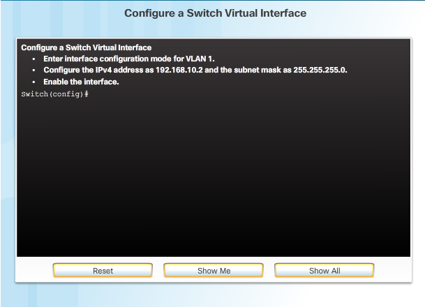
Syntax Checker - Configuring a Switch Virtual Interface

Use the Syntax Checker in the figure to practice configuring a switch virtual interface.

Switch Virtual Interface Configuration

To access the switch remotely, an IP address and a subnet mask must be configured on the SVI. To configure an SVI on a switch, use the interface vlan 1 global configuration command. Vlan 1 is not an actual physical interface but a virtual one. Next assign an IPv4 address using the ip address ip-address subnet-mask interface configuration command. Finally, enable the virtual interface using the no shutdown interface configuration command.

After these commands are configured, the switch has all the IPv4 elements ready for communication over the network.

Click Play in the figure to view a video demonstration of how to configure a switch virtual interface.

Click here to read the transcript of this video.

Monday, December 26, 2016

Packet Tracer - Configuring Initial Switch Settings

In this activity, you will perform basic switch configurations. You will secure access to the command-line interface (CLI) and console ports using encrypted and plain text passwords. You will learn how to configure messages for users logging into the switch. These banners are also used to warn unauthorized users that access is prohibited.

Packet Tracer - Configuring Initial Switch Settings Instructions

Packet Tracer - Configuring Initial Switch Settings - PKA

Capture Configuration to a Text File

Configuration files can also be saved and archived to a text document. This sequence of steps ensures that a working copy of the configuration file is available for editing or reuse later.

For example, assume that a switch has been configured, and the running configuration has been saved on the device.

  • Open a terminal emulation software such as PuTTY or Tera Term (Figure 1) connected to a switch.


  • Enable logging in the terminal software, such as PuTTY or Tera Term, and assign a name and file location to save the log file. Figure 2 displays that All session output will be captured to the file specified (i.e., MySwitchLogs).


  • Execute the show running-config or show startup-config command at the privileged EXEC prompt. Text displayed in the terminal window will be placed into the chosen file.


  • Disable logging in the terminal software. Figure 3 shows how to disable logging by choosing the None session logging option.


The text file created can be used as a record of how the device is currently implemented. The file could require editing before being used to restore a saved configuration to a device.

To restore a configuration file to a device:

  • Enter global configuration mode on the device.


  • Copy and paste the text file into the terminal window connected to the switch.


The text in the file will be applied as commands in the CLI and become the running configuration on the device. This is a convenient method of manually configuring a device.

Saturday, December 24, 2016

Save the Running Configuration File

There are two system files that store the device configuration:

  • startup-config - The file stored in Non-volatile Random Access Memory (NVRAM) that contains all of the commands that will be used by the device upon startup or reboot. NVRAM does not lose its contents when the device is powered off.


  • running-config - The file stored in Random Access Memory (RAM) that reflects the current configuration. Modifying a running configuration affects the operation of a Cisco device immediately. RAM is volatile memory. It loses all of its content when the device is powered off or restarted.


As shown in the figure, use the show running-config privileged EXEC mode command to view the running configuration file. To view the startup configuration file, use the show startup-config privileged EXEC command.

If power to the device is lost or if the device is restarted, all configuration changes will be lost unless they have been saved. To save changes made to the running configuration to the startup configuration file use the copy running-config startup-config privileged EXEC mode command.

 
Design by Free WordPress Themes | Bloggerized by Lasantha - Premium Blogger Themes | Best Web Hosting